Better Box Blank Feeder
Introduction
Better Box Company is a manufacturer and distributor of plastic boxes based in Grey, Maine. What makes Better Box unique is that the owner, Stephen Holdtman, has designed a manufacturing system that automates the entire manufacturing process from a blank sheet to a complete thermo-formed and glued product.
First, stock plastic is rolled through a cutter, making smaller rolls of blank sheets at a specified width. Then, the smaller rolls are fed through a leather cutting machine using a custom-made linkage. The leather cutter has a unique die that cuts discrete blanks based on the size and design specified by the customer. After a blank is stamped, the machine strips away the excess material and feeds the piece of plastic into a machine the folds the sides of the sheet and glues them together, creating one half of a complete box. Along the way, unique writing and logos can be hot-stamped onto the blank sheets, adding another element of customization for clients.
This unique manufacturing process enables Better Box to process large orders of boxes quickly with little manual labor involved. The assembly line can often be staffed by one skilled operator and a laborer to sort and stack boxes as they are completed. In fact, the majority of labor in this process is dedicated to packing the product for shipping.
The Problem
Traditionally, Stephen has used pneumatic rotary table actuators to power the linkage that feeds the blank rolls of plastic through the die cutter. The table actuators are advantages because they are able to perform an accurate 0-180 motion stop-stop for many cycles and they produce a nice smooth motion to limit the wear and tear on the linkage of the machine. While they are perfectly effective for the job, Stephen is interested in exploring alternatives for these devices based on a couple limiting factors. To used the actuators in his assembly line, Stephen has to modify them to use hydraulic fluid instead of pneumatics, otherwise the compression of the air in the cylinders of the device would cause inconsistencies in the motion of the device. While they can operate under these conditions, the seals between the pistons and cylinders of the devices begin to break down over time which causes hydraulic fluid leaks on the assembly line. This is undesirable because it becomes increasingly costly as the seals continue to break down and it makes a mess. Ultimately, the devices have to be replaced after a few years of operation.
I was contracted by Stephen to explore the possibility of using electronics instead of hydraulics for the blank feeder mechanism as an opportunity to test my skills in mechanical design and explore the process of turning an idea into a functional device.
Problem Definition
To determine a problem statement, objectives, and goals for this design, I consulted with Stephen and observed the current solution on the machine.
Problem Statement
The new device must use as little torque as possible to maintain a safe working environment for Better Box employees. No part of the device should operate at greater than 300RPM. The device must be compatible with the current electrical timing controls on the machine and the current swing arm that pulls the plastic sheets through the blank stamper. Lastly, the new device should be easily removable from the machine in case it must be serviced or replaced with the current solution.
Goals
Lowest possible torque
Operating speed no greater than 300RPM
Easily removable from machine
Objectives
Replace current hydraulic/pneumatic solution with an electrically powered device
Incorporate current electrical timing controls and swing arm into new device
Conceptual Design
Drivetrain
Based on the physical constraints imposed by the mounting requirements of the device and likely interference with the machine frame, it is useful to incorporate a drivetrain. The drivetrain will allow the motor to be mounted in a more convenient area. Another advantage to using a drivetrain in this case is that gearing can be introduced between the motor and the swing arm, which will allow the use of a lower torque motor.
For this design, a timing belt-train is chosen over meshed gears or a chain drive. Meshed gears require close proximity, which would negate the primary desired function of the drivetrain in this case. A chain drive would allow the motor to be a larger distance from the driven wheel, however a chain would introduce more inertia to the system, which would negate the advantage of gearing to reduce motor torque. A timing belt-train would be light, and wouldn’t be prone to slipping under the high acceleration conditions of this motion-unlike a v-groove or friction belt.
Mounting
The original device is mounted to the blank stamper via an integrated rail and fastened with machine screws. The new device can be mounted to a single plate, which will be attached to the machine in the same manner. This design will ensure that the prototype can be easily mounted and dismounted for testing and client needs.
Electric Motor
To power the device, an electric motor will be used as per client spec. A stepper motor is advantageous for this application. Unlike other DC motors, steppers have a large quantity of “toothed” electromagnets. Rotational motion is achieved by sending electrical pulses to each magnet in turn, which allows fine positional control of the driveshaft. Steppers also tend to have more torque at startup and low speeds compared to other electric motors, which will be essential for achieving the acceleration needed to integrate this device into Better Box’s current throughput.
Motor Control
To interface with stepper motor with the existing machine controls, it will be necessary to interpret analog voltage signals produced by the machine and use these signals to activate the motor. An Arduino provides a simple and effective avenue to control the device. With the proper motor controller, coding libraries, and voltage sensors, the Arduino will allow the acceleration of the motor to be finely tuned to the machine rhythm.
Detailed Design
Note: This section is taken directly from design documentation delivered to client, which included a background section. The background has been omitted from this page to trim down length. If there are any references in this section that are not present on the page, I can present them if you may be interested. Please feel free to reach out with any questions, my information is on my contact page.
Design Overview
The design will be mounted on an aluminum plate which will mount to the machine on one the long sides. The plate will sit upright with a mounted stepper motor, a motor controller, Arduino, and belt drive consisting of a driven, idler, and driving pulley and a timing belt. The driving pulley will be mounted to the motor and tensioner pulley will be mounted to the plate with a tensioning device to allow for easy installation of the timing belt and ensure that there is little play in the system. The driven pulley will mount to the plate on a bearing, and the bar will be mounted to the driven pulley through a piece of the old table spinner to which it was mounted. The current device already has holes for the shaft, and it has other holes that can be used to attach it to the driven pulley through and adapter. The motor controller has holes to mount it to the plate, and the Arduino must be mounted with consideration towards electrically insulating it from the aluminum plate.
Drawing 1: Motor Subassembly
Motor Subassembly
This machine requires an industrial grade stepper motor. The Nema23 (23HS45-4204S) (#1.1) is a capable industrial stepper with a holding torque of 3Nm (26.55 lb-in) and a 1.80° step angle with a non-accumulating accuracy of ±5.00%. It uses a two-phase design with four inputs to control direction and rotational speed. It uses 4.20A/phase and weighs 424g (0.93lbs). The output shaft is ᴓ10mm x 20±0.25mm and features a square mounting pattern with four M5x10mm mounting holes spaced at 47.14±0.2mm on the output face of the motor (Figure 7).
In order to align the motor pulley with the rest of the belt drive, it will be held to base plate through an adapter plate (Drawing 2)(#1.2) and two spacers (Drawing 3)(#1.5). Four holes will be drilled onto the adapter plate to attach the motor with four M5x20mm hex nuts (#1.3) and four M5 nylon locknuts (#1.4). The adapter plate and spacers are attached to the main baseplate and the motor adapter plate with four ¼”-20x1.5” hex bolts (#5.6) and four ¼”-20 nylon lock nuts (#5.4).
Drawing 2: Motor Adapter Plate
Drawing 3: Motor Spacer
Figure 7. Nema23 Data Sheet
Motor Control
Figure 9: DM542T Spec Sheet
The Nema23 requires a motor controller to regulate power consumption and interface the control signal from the Arduino (#2.5) with the motor. A DM542T stepper drive controller (#2.1) designed by Stepper Online and manufactured by Leadshine is suitable for this application. This device has a peak output of 4.2A at 20-50V. The motor controller has 4 ø3.5mm holes that can be used to mount it to the plate with 4 M3x20m machine screws (#2.2), M3 washers (#2.3), and M3 locknuts (#2.4) (Figure 9). This motor controller allows for adjustable output current and micro-stepping.
Adjustable Features
The adjustable current is useful because it enables the driver to be used with a variety of steppers. In this case, the controller will be operating at the highest dynamic current setting of 4.2A, which is achieved by setting dipswitches one through three of the controller dipswitches to the off position.
The adjustable micro-stepping is a feature that allows the user to configure the amount of steps/rev thus determining the resolution of the motor. The lower the number of steps per revolution, the output pulse per resolution, so the motor can rotate faster with less fine positional resolution. On the other hand, a higher microstep count allows for much higher positional accuracy, but more pulse per resolution which can affect the maximum rotational speed of the motor.
Another consideration when selecting microstep resolution is that the output torque of the stepper depends on the speed of the motor in pulses per second. Torque decreases linearly with increasing pulse frequency. At the lowest resolution of 1microstep/full step the achievable holding torque is the same as the specification of the motor, but at 2microsteps/full step, the holding torque is about 70% of the manufacturer specification (Budimir, 2003). Therefore, it is prudent to use micro-stepping sparingly in applications where the maximum torque of the motor is desired.
Determining Microstep Resolution
This application involves a simple 180° motion, and it is desirable to maximize amount of torque at the output shaft to ensure the device is reliable. The manufacturer specified accuracy of 1.8°/step±5.00%, the maximum error of the device with 1microstep/full step would be 0.09° which is well within an acceptable range of error for the desired motion. Therefore, the motor controller will be set to the lowest possible microstep setting of 2microsteps/step (400steps/rev) by setting dipswitches 5-8 to off-on-on-on positions. Based on this information, the expected output torque of the Nema23 is recalculated. The estimated holding torque due to 2microsteps/step is 70.71% of the original value (Budimir, 2003). Therefore, the effective torque of the Nema23 for this application should is estimated to be no more than 2.1Nm (18.6in-lbs).
Arduino Logic Control
An Arduino Uno logic board is used to interface the signals between the machine and the motor controller of the blank feeder.
Figure 10: Connections between Arduino and motor controller (DroneBot Workshop, 2019)
The motor controller has four control inputs, DIR+/- and PUL+/- which are used to control the speed and direction of the motor. There are also optional ENABLE+/- terminals that can be used to control power to the motor, but these will not be used for this device. The device is connected to the Arduino via the common-anode configuration, so the DIR+ and PUL+ terminals are connected to the +5V power terminal on the Arduino (Figure 10). The PUL- and DIR- terminals are connected to two separate digital output pins on the Arduino which can be toggled between Low (0V) and High (5V) output using the logic board.
An input signal is interpreted as the difference between a positive and negative terminal on the motor controller. This gets a little tricky because the positive terminal of the motor controller is connected to a constant +5V signal. Since the control signal is the difference between the two terminals, a high control signal at the motor controller (+5V) is achieved by setting the corresponding output on the Arduino to Low (0V). Conversely, a low control signal (0V) at the motor controller is obtained by setting the corresponding output on the Arduino to high (+5V) since the measured difference between the positive and negative terminals of the motor controller will be 5V-5V=0V (DroneBot Workshop, 2019).
Figure 11: DM542T Common Anode Connections
AccelStepper is a common library for Arduino that simplifies stepper control and features acceleration, deceleration, a multitude of control interfaces, and discrete timing.
Figure 12: Initialize Stepper control
AccelStepper has built in functions that makes Arduino a much more capable controller. For this program, first initialize AccelStepper and MultiSteppper. Then set up a stepper using the stepper(<type>,<PUL>,<DIR>) function, into which type “1” is passed and the two pins of the stepper driver, 7 and 6.
Then, introduce two integers for the input from the machine called gotoZero and gotoPi on pins 2 and 3. Also introduce an integer to represent a pin that controls a status LED called led which is on pin 13. The status LED is on when the program thinks the stepper has reached its desired position. Note, there is no position sensor in this system, so the LED only represents whether the stepper driver has received enough input pulses, if the motor is slipping, this light will be on despite the stepper being out of position. A magnetic positions sensor could be introduced to automatically correct the position of the stepper if there is ever slip, but it brings an unwanted level of complexity to the device at this stage.
Figure 13: initialize variables
It is also prudent to initialize three variables that will be used to store information during each cycle of the program. zeroState will store the value (LOW or HIGH) from the gotoZero input pin, and piState will store the value form the gotoPi input pin. place will store the value (in steps) of the position the stepper should be in based on the input value in zeroState or piState.
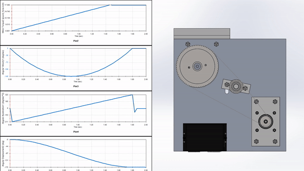
Next, in the setup function, set the max speed and acceleration of the motor in steps/s and steps/s2 using the setMaxSpeed and setAccleration functions from the AccelStepper library. The maximum speed of the motor is limited by two factors. First, the stepper driver can only handle a pulse length and spacing of 5μs (or 200,000pul/s, derived by inverting the wavelength). Second, the processor in the Arduino is only capable of looping the program at a certain frequency, which the author of AccelStepper claims to be 20μs (50,000pul/s). Based on observation of the device, the average speed of one half rotation is 1.8s. The motor must also spin four and a half times to get an equivalent angular displacement from the driven belt. For the stepper driver setting of 2microsteps/1step and a 1.8°/step motor means that one half-rotation is 200steps. This means that the motor must make an average speed of ~100steps/s. Given a triangular velocity pattern, this means the motor must achieve a maximum velocity of 200steps/s.
Figure 14: Setup function for program
Also, set gotoPi and gotoZero as pullup inputs using the pinMode function. This tells the Arduino to use its internal 20kΩ resistors which reduce the effects of input noise on discrete inputs such as switches. The pullup will automatically set the value of the input to HIGH if there is no input signal and LOW if there is +5V into the pin (Gammon, 2016).
Next, in the loop function, the program checks the state of the two input pins and writes them to the state variables. Then, the program tests to see if zeroState is LOW and piState is HIGH, and if this is true then it writes -450 to the place variable, which corresponds to the full left position of the machine arm. If this is untrue, the program continues to execute.
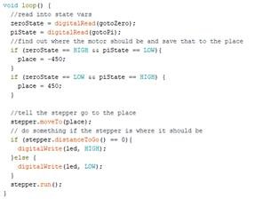
Figure 15: Loop Function of Stepper control program
Next, if zeroState is HIGH and piState is LOW, the program sets the value of place to the full right position of the motor (+450 steps). If this is untrue, the program carries on.
Then, the motor calls the moveTo function, which is passed the value of place, telling the program that it should direct the stepper to value of place (full left or full right).
After this, there is a conditional statement that controls the status of the LED using the distanceToGo function from AccelStepper, and the loop function is concluded by the stepper.run() statement, which directs the stepper to move to to the position passed in the moveTo function unless it is already there. stepper.run() is powerful because it automatically determines acceleration based on the current speed and position of the motor (McCauley, 2020).
Wiring and Power Supply
Wiring for the device is relatively simple. Connect the two positional inputs from the machine to digital pins two and three of the Arduino. These are connected via 24V to 5V DC transformers to bring the output voltage from the machine down acceptable range of input voltage for the Arduino. Connect the PUL- (green wire from the stepper driver) to digital pin seven and the DIR- (purple wire from the stepper driver) to digital pin six. Connect PUL+ and DIR+ to the two +5V connections on the board. The motor driver is powered by a 24V, 6A power supply. The Arduino is powered by a 9V, 1A power supply. Do not mix these up, trust me.
Belt Drive
A timing belt is used to link the drive motor to the blank feeder bar because it is lighter than a chain or gear mechanism while ensuring the positional accuracy is maintained between the motor and the device.
The initial calculations for gear ratio were conducted based on the client’s wish to have the motor operating around 300RPM.
Based on these parameters, a gear ratio of 18:1 was calculated, which would mean that the output pulley would have to be eighteen times the size of the input pulley. Unfortunately, this gear ratio is not achievable with a single stage reduction. While it would be possible to achieve the target speed of the motor using a dual-stage belt train, this would increase the inertia of the mechanism.
After discussing this shortcoming with the client, it was decided to specify the gear ratio based on the torque requirements of the system rather than attempting to obtain a certain target speed for the motor.
The original hydraulic device that will be replaced operates at 100psi according to the designer. This means that the original rotary table device is outputting between 28in-lbs (3.19Nm) and 34in-lbs (3.82Nm) of torque. As discussed in sections one and two, the Nema23 is expected to have an effective torque of 18.6in-lbs (2.1Nm). Therefore, to achieve the desired output torque, the gear ratio must be at least 1.82 (Equation 5).
Drawing 4: Driven Pulley Assembly
This figure is verified by physically estimating the forced exerted at the end of adjustable bar. While the device was active and holding the bar in position, a scale was pressed against the bar using a stock piece to provide a discrete point of application at the end of the bar. The reading on the scale, 10lbs, was multiplied by the distance between point of application and the axis of rotation, 8in, which means the device was exerting about 80in-lbs of torque. I’m glad we measured, because I’d rather not underestimate this figure. Using 80in-lbs as τout in the gear ratio equation (Equation 5), it is found that the gear ratio should be at least 4.3.
McMaster-Carr supplies belts and pulleys. The driving pulley must fit the shaft of the motor which is 3/8” (9.5mm). McMaster-Carr offers XL Series Corrosion Resistant hub less pulleys that are machined from anodized aluminum. The smallest available size is a 16-tooth pulley. This will be the driving pulley (#3.1), which means a 72-tooth pulley must be used as the driven pulley (#3.2) to obtain the minimum required gear ratio.
Drawing 5: Driven Pulley Shaft
The driving pulley may be mounted directly to the shaft of the motor using the set screw built into the pulley
The driving pulley is designed to fit a 3/8” shaft, and the Nema23 output shaft is ¼” (9.5mm) (Figure 7). Therefore, a 3/8” thick bushing (#3.3) must be made to fit the motor shaft to the input pulley.
The driven pulley is mounted to a ø3/8x3 3/16” shaft (Drawing 5) (#3.4) which is mounted to the base plate using two low profile pillow block bearings (#3.5). Two 3/16-18x1” hex bolts (#3.6) and nylon lock nuts (#3.7) are used to secure the pillow block to the main base plate.
Drawing 6: Machine Adapter Hub
Also mounted to the driven pulley shaft is an adapter to connect the machine arm to the output shaft (#3.8). The hub adapter (Drawing 6) is ø2.1375”x ¼” and has eight ø3/16” through holes arranged radially at ø.972” on the hub face. There is a 3/8” through hole drilled at the center to mount the adapter to the shaft. The final part of the driven pulley assembly is the set-screw collar that holds the adapter plate (#3.9).
The final part of the belt drive is the timing belt (#3.10), which is a 3/8”x28” XL series neoprene timing belt with teeth on both sides.
Tensioner
Drawing 7: Tensioner Assembly
To maintain the appropriate amount of tension in the belt drive and afford easy installation and removal of the timing belt, the belt drive will incorporate a third pulley, an idler pulley (#4.1). the pulley is mounted to simple ø1/2”x1.75” shaft (#4.2) that is welded to a mounting plate (#4.3). The pulley held to the shaft using a set screw collar (#4.4) and is positioned on the shaft using a plate side spacer (#4.5) and a collar side spacer (#4.6).
The mounting plate is attached to the base plate with two ¼”-20x1” hex bolts (#5.2), washers (#5.3), and nylon lock nuts (#5.4). One of the mounting holes on the base plate is a ¼” clearance hole, and the other is a 3/8” slot to allow the plate position to be adjusted. By adjusting the position of the plate, the user can increase or decrease the tension on the built due to the idler pulley.
The span length of the belt drive (P) is 9.21in, therefore the belt must be able to deflect at least 0.144in (Equation 6). The attachment points on the baseplate will be drilled/milled in positions that will the ensure idler pulley can deflect the belt between 0in and 0.25in to ensure a decent range of adjustability.
Base Plate
Drawing 8: Base Plate Assembly Drawing
The base plate assembly provides structural support for all the components in the system. There is a main base plate Drawing 9)(#5.1) and four ¼”-20x1” hex bolts (#5.2), ¼” washers (#5.3), and ¼”-20 nylon lock nuts (#5.4) that attach the motor adaptor plate to the main base plate.
The main base plate is mounted to the machine with a 1.5”x6”x2” channel bracket ( Drawing 10)(#5.5) via two ¼”-20x1” hex bolts (#5.2), ¼” washers (#5.3), and ¼”-20 nylon locknuts (#5.4).
Drawing 10: Channel Bracket
Drawing 9: Main Base Plate
Implementation
Overview
Once a detailed design report was presented to Stephen, he gave approval to order parts and stock to begin fabrication. The prototype design evolved rapidly while it was being built. While working with Stephen, his machines, and my own drawings, I learned valuable, hands-on lessons about design for manufacturing and assembly.
I found that in many cases, I had over designed components and assemblies. It quickly dawned on me, how difficult and sensitive machining can be, and I learned hands-on what it takes to fabricate components to even within 1/2” tolerance. I realized, based on how sensitive manual machining is, that reducing machining steps is an essential part of a good design.
I also found that fitting components together looks a lot easier on paper than it is in real life. I may be able to measure and place hole positions down to the thousand in Solidworks with a few clicks, but replicating that precision in a shop - even with calipers and precision marking tools - takes skill and patience. Once again, I realized the true significance of a lesson I was taught in my design classes, but had not yet experienced myself: use as few fasteners as possible.
Lastly, my biggest lesson was in over-designing the whole prototype. I found that I had included whole subassemblies in this device through hands-on optimization. Through the process of fabricating and assembling this machine, I learned how to make the most out of fewer components. To put it in pithy: K.I.S.S (keep it simple stupid)
Detailed Changes
Motor and Drivetrain
The most significant change to the prototype arose from realizing that the function of the tensioner assembly could be replicated by mounting the motor assembly to the base plate with slots instead of holes. By milling slots into the baseplate, the motor assembly can be moved towards the driven pulley so that the belt can be easily slipped into place. Once the belt is in place around the pulleys, the motor assembly is moved away from the driven pulley until there is enough tension in the belt for the teeth to engage with the pulleys. This reduced a lot of complexity in the fabrication of the device.
Mounting
The original detailed design used a hub and shaft collars to connect the driven pulley assembly to the swing arm of the machine. While fabricating and testing the prototype for fitment, it became apparent that this assembly was too bulky to fit onto the machine. The adapter hub was removed altogether, and instead holes were drilled directly into the driven pulley to attach it to the swing arm.
The driven pulley was also turned in a lathe to remove excess material from the body to reduce its rotational inertia.

Final Prototype
After a summer of design, fabrication, iteration, some cursing, and a lot of fiddling, Stephen and I were able to mount a final prototype to the machine for a successful test.