Lightweight FDM Bridge
Introduction
The Class
ENG ME557: Additive Manufacturing is an exciting class dedicated to teaching students the latest and greatest in commercial and industrial 3D printing technology. The class features two lecture sections where professor Chomyszak explains the benefits, drawbacks, and guidelines for material deposition, vat polymerization, and metal melting and sintering techniques. The lab includes a lab section, and the first project is to design and FDM print a bridge.
The project
The bridge must be able to span 450mm, hold 10kg, and no piece may be longer than 230mm. There is a mass supported/mass of bridge figure of merit, and points for aesthetics as voted on by the class. The weight is suspended by a hanger which can be supported by the bridge or by a 5x100mm pin. The pieces must be made entirely out of Matterhackers, Pro Series, PLA, 1.75mm. The pieces can be held together with 5x10mm steel pins.
Concepts

Pre-sectioned Concept with Lightweighting Features
The team went with what a member referred to as a “shotgun approach” to concept development. We were all excited to explore the possibilities of FDM in this application and brought different ideas to the table. I started by modeling out a sectioned bridge with the intent to topology optimize each section with generic loading characteristics. Another member modeled out a basic arch design and worked on joint development. We all quickly agreed that an arch design was an ideal candidate for this application because they’re sturdy (exemplified by the multitude of ancient roman bridges that still continue to stand) and they don’t require complex joints. In my own designs, I focused on trying to limit the amount of load being carried by joints by having large contact faces designed to pass a distributed load between the parts. In this regard, any mechanical joints would only be necessary to keep the bridge together and would not be carrying significant amounts of the 10kg load.

Arch Concept with Basic Lightweighting
At one point, another member and myself realized that we would get better optimization results by modeling out a full span concept, applying loads, and simulating rather than trying to optimize individual pieces. This was based on advice from a guest lecturer that topology optimization works better when given a large, generic build volume. Inspired by lecturer, we modeled a full sized arch concept and I used nTopology to optimize the generic design for the expecting loading conditions.
Topology Optimization
I used Altair Inspire and nTopology to conduct topology optimization on both individual bridge sections and a full span concept. Although these designs didn’t become fully realized in the final design, they helped show the team what an optimal arch design would be for the expected loading characteristics
Inspire

Topology Optimization in Altair’s Inspire
Inspire was the first software package demonstrated to the class, so I used it primarily to simulate the early, sectioned concepts for the bridge. Inspire is a handy tool for running quick and simple topology optimizations. It allows the user to easily simplify geometry, apply materials, select a build volume, constrain and load partitions of the body, and constrain results based on symmetry and manufacturing specifications, including print orientation constraints for overhangs. Inspire offers displacement, strain, stress, factor of safety, and tension/compression views for results which is really helpful for initial ideation since it enables the user to easily understand how stresses are traveling through the structure based on topology and loading.
nTopology
nTopology is in a league of its own. While the learning curve is steeper, the block-based approach to program design allows the user to control almost every parameter of their simulation. I really enjoyed working with nTop because I could very finely control my simulation parameters and quickly complete simulations.
nTop is also a powerful lightweighting tool that enables users to lattice and hollow out parts. I had the opportunity to use nTop to create hollow parts with lattice infills that are driven by FEA results. Using output data from a static test, I can create variable thickness shells and beams for lattices to effectively control for the density of parts in regions of high and low stress. While these designs didn’t make the final cut, they are a great example of what is achievable with nTopology and why it’s so powerful for additive manufacturing. It’s also a lot of fun.
Preliminary Design and Initial Testing

Dovetail Joint
After conducting a topology optimization on the full sized model, I split it into sections using Solidworks and passed the files along to the team. Since time constraints were beginning to loom, the team decided to print a beefier, simplified version of the topology optimized model for our initial testing to ensure the print would succeed and we could test a bridge with a high likelihood to hold the full 10kg load.
Unfortunately, the team didn’t realize that the bridge would only be supported from the bottom and we could not use the edges of the span to constrain the bridge longitudinally. This significantly alters our expected loading characteristics because it means that the load of the bridge can push the legs outward as it deflects the middle section, causing the internal stresses in the bridge to differ from our simulated results and putting unexpected stresses on the joints.
Final Design

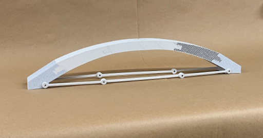
Final Bridge Submission
After realizing that our biggest issue with the current model was the “bowing” effect caused by unconstrained longitudinal movement of the feet, the team realized that a simple and effective solution was to include tension rods spanning the bridge. The tension rods keep the feet of the bridge constrained so that the real world loading characteristics match the design intent of the bridge. A team member also redesigned the section joints inspired by K’nex to be much beefier. The results of these changes were that the bridge was able to shrug off the 10kg load during testing. The team also managed to have one of the lightest bridges in the class at 325g, but we were left feeling like we could’ve gone further with the design.
Conclusion
Based on my experience with this project, I learned some lessons on how to approach design projects in a more time-effective method.
Fail Fast
I realized that with a rapid prototyping tool like 3D printing that can churn out parts at minimal cost, it’s best to keep the printer active as much as possible in order to get quick feedback on design choices. In particular, this project involved a lot of unknowns, so teams that tested their parts early were able to reach more refined final designs.
Test the Hell Out of It
It seems simple, but the only way to know exactly how a part is going to perform in real is to simulate accurate loading conditions in real life (and then some if you have parts to spare). Testing unknown parameters such as material properties and how topology will influence loading early on (as mentioned above) gives confidence and informs further iterations.
Divide and Conquer
When working with group projects, it’s important to have clear delegation and communication of ideas. Group brainstorming is lots of fun, and a good way to come up with creative ideas in early design stages, but it’s imperative that when the brainstorming is done, discrete tasks with reportable deliverables are used to manage progress towards a testable prototype based on the concepts that have been brainstormed. In other words, make sure everyone is working to produce a single testable prototype in conjunction in order to take advantage of rules #1 and #2.