Designing wheel assemblies for a Formula Hybrid car
As the wheels team lead for Terrier Motorsport, my responsibility is to design, fabricate, and assemble wheel assemblies for our projects. For our current build, I had the pleasure of getting to design my own system from the ground up, beginning the problem definition phase in the Summer of 2020.
Some Background
What is a wheel assembly?
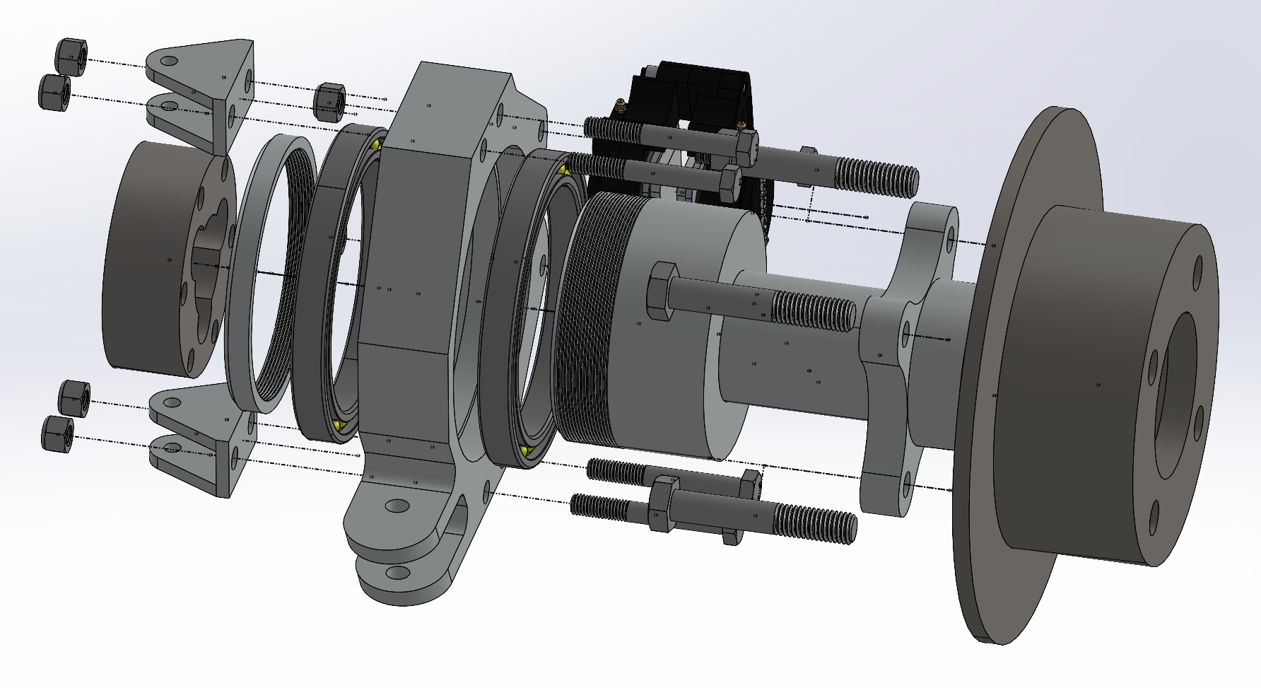
Anything between the suspension and the tires is included in the wheel assembly. The primary components are,
Uprights
Uprights are the go between for the suspension and the wheel. Suspension components such as the control arms and tie rods interface with the upright to secure it to the vehicle.
Hubs
The hubs connect to the upright via wheel bearings. Think of the hub like an extension of the wheel. The hub connects the wheel to the upright in a way that allows the driver to control the vehicle.
Brakes
Brake calipers are attached to the upright. When the driver actuates the brake pedal, hydraulic pressure extends pistons which are connected to brake pads. The brake pads are designed to generate as much friction as possible when in contact with the rotors.
Brake rotors attach to the hub. When the driver actuates the brake pedal, the calipers squeeze the rotors, creating a friction force which dispels the kinetic energy of the vehicle into heat.
Problem Definition
The first part of any design is understanding what the final product must accomplish. It’s also important to know what constraints the design will face and what objectives to seek in order to create the best possible solution to the problem defined by the task at hand.
What’s challenging and interesting about wheel assemblies is that they bring together many of the vehicle systems at the wheels. Optimizing the design of a wheel assembly is crucial to ensure that the car can meet its design objectives.
For Terrier Motorsport’s second build, Scarlett, the performance specifications are to have an acceleration time within three to four seconds, an even weight distribution along the length of the car, an overall weight of 300kg including a 70kg driver, and a top speed of no less than 80kph. Finally, the vehicle must be completed by the spring of 2022.
Project Timeline
Creating a comprehensive timeline for the project from the problem definition phase to the final assembly is an important part of any design. A timeline must include design reviews and take contingency into account in order to accurately predict the completion date for the project.
Conceptual and Preliminary Design
Immediately following the completion of a problem state, the conceptual design phase is a time to accumulate ideas and solutions to the challenges the product faces. Basic models are generated, and conceptual approaches are weighed until a preliminary design concept is reached. Finally, the material is presented to the club for review.
Detailed Design
I like to call detailed design the nuts and bolts phase of the design process. In detailed design, the concepts from the previous phase become a reality. The most difficult part of this phase during this design process was fitting everything together.
Manufacturing and Assembly
Manufacturing in these times is a big question. Currently the club has very limited access to our workspace. While it is possible to have our parts manufactured at the campus machine shop, it would not be possible to assemble the full wheel assembly and attach it to the vehicle.
Problem Statement
The wheel assemblies for Scarlett must provide a mounting interface for the control arms, tie rods, and wheels. There must be positive locking between the wheel hub and the upright as per Formula Hybrid safety regulations. It will be ideal for the wheel assemblies to be lighter than the previous car, if not, equal in weight. In addition, it is desirable for the wheel assemblies to be easily serviced.
Conceptual Design
Functional Decomposition
Functional decomposition is a method of breaking down the functional requirements of a product to its most basic components. In conceptual design this is a helpful process to ensure the conceptual design of the product addresses all the requirements in the problem statement
Pugh Matrices
Pugh matrices are a method of weighing different design concepts for a product. In this build, I used a pugh matrix to weigh prefabricated components of the wheel assemblies such as the brakes, wheels, and tires. Characteristics which determine value to our build are listed on the left side, and different candidates are in columns. All candidates are scored in reference to the component being used in the previous car (current). This is advantageous because it allowed the team to determine if it was worth ordering new components. If a new component wouldn’t have a discernible performance improvement from the previous generation, then we can use a part we already have paid for to save expense on the new car.
Tire Selection
For tire selection, we were concerned the weight of the tires. Typically tires are the heaviest part of any wheel assembly, so mitigating weight increase from the previous car to the new car is important for our goal to maintain or reduce the weight of the assembly compared to the previous car. Cost is also an important consideration. A problem from our previous car was that it was more expensive than most cars at our competition. One of the club’s overall goals is to reduce cost as much as possible. Tread width is the metric for which we are able to measure performance of the tire. In general, it is desirable to have larger tread width since that corresponds to more of the tire in contact with the road at any time. However, as tire size increases, it takes more friction between the road and the tires to increase the temperature of the tires. Performance tires especially must be within recommended operating temperature to perform as expected, so it is also important to ensure that the chosen tires balance size with the expected weight and downforce of the vehicle. For Scarlett, the aero team is expected to produce 1000N of downforce.
Preliminary Drawings
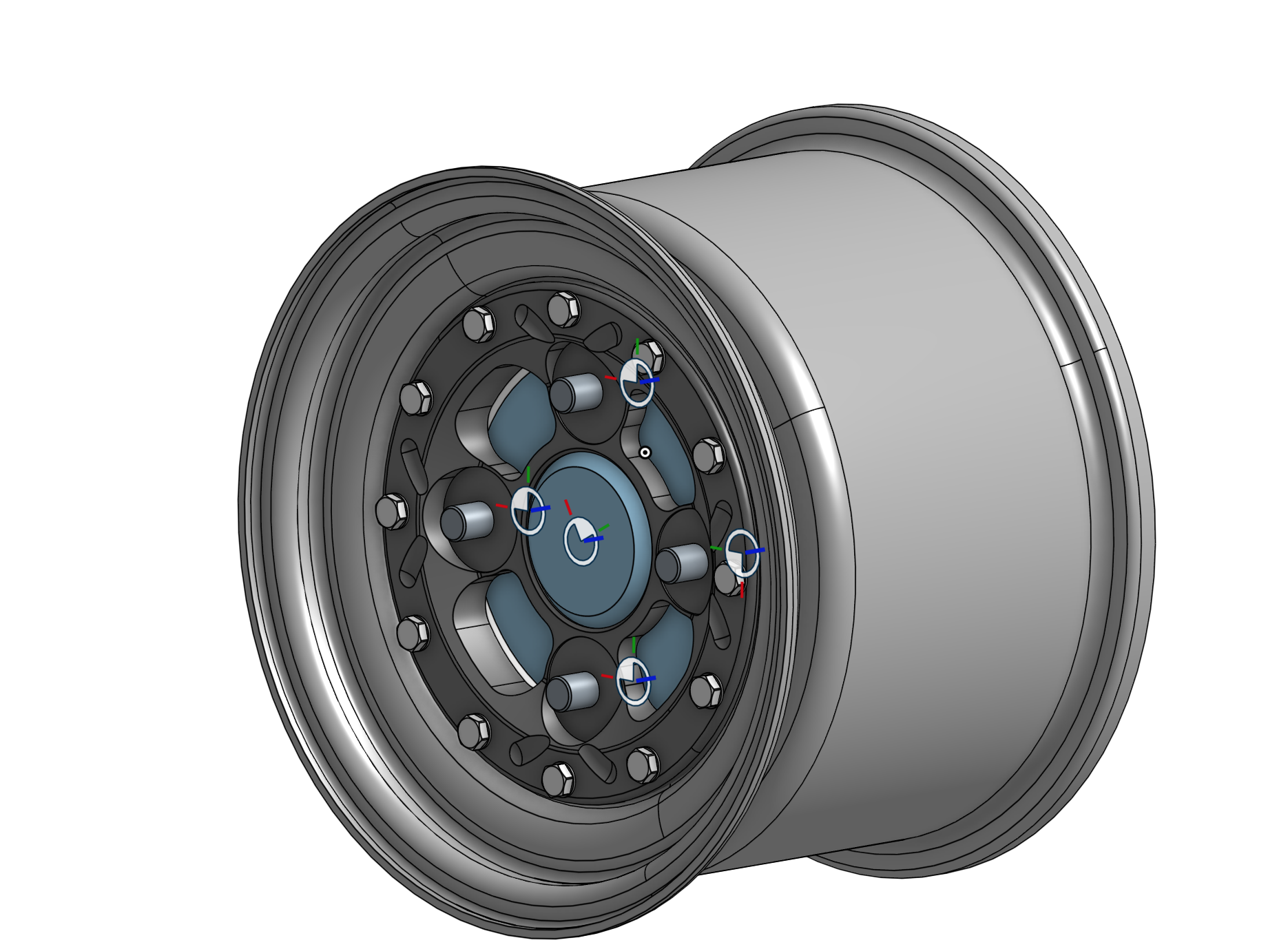
Rim Selection
To find the right rims for the car, I looked at two different manufactures who make tires specifically designed for Formula Hybrid cars. Our previous build used Braid rims. However, I found an alternative in the form of the Keiser 10i rims. Machined from aluminum, these three piece modular rims offer unparalleled lightness and versatility. Keiser allows full customization of rim diameter, width, lug bolt pattern, and offset. Customization is key for this build since it allows the wheel assemblies to be versatile to design changes made while the car is in detailed design.
Brake Caliper Selection
Brake caliper selection is informed by the expected size of the tires. Many alternatives for the brake calipers on the current vehicle were considered. Ultimately, I decided to use the Wilwood GP200 calipers that are on Stella because it would save cost, and the brakes on Stella have performed well in testing.
Detailed Design
Material Selection
Materials are a crucial element of any product’s success. For the main components of the wheel assembly, the priority is to minimize cost and maximize ductility and toughness. While other variants were considered, AL7075-T6 aluminum is the de facto choice because it has toughness comparable to steel but with much lower density. This aluminum allow is being used for the uprights, hubs, and universal components on the wheel assemblies.
Upright Design
Front Upright
Rear Upright
In addition to fitting within the inner diameter of the Kieser 10i rims, the front uprights must be able to mount to the suspension of the vehicle. The control arms are required to be a certain distance from each other at the mounting interface with the uprights. The distance between the control arm mounting points was determined to be 153.24mm apart. Since it is ideal to limit the size of the uprights to reduce material, the height of the front uprights is 168.24mm. This height is as small as possible while also providing adequate strength for the mounting interface.
Two M8 screw clearance through holes will be drilled symmetric about the horizontal and vertical axes and 25 and 153.24mm apart respectively. These holes allow for M8 hex bolts with positive locking to secure mounting brackets for the control arms to the upright.
The next primary feature of the uprights is the hole cut centered on the height and width of the part. The chosen bearing for the wheel assemblies is the SKF 14131/14276 tapered roller bearing. The bearing has an outer diameter of 69.012mm with a normal shaft tolerance of +/-16micrometers. The bearing will be press fit into the center hole which will have a diameter of 69.0mm with an ISO H7 hole tolerance. The width of the front upright is 75mm to accommodate the diameter of the hole. The thickness of the front upright is 46mm. This is to allow the two 15.875mm wide tapered roller bearings to be press fit into the center hole. This thickness also accommodates a central ridge which is 2.5mm tall and 6mm thick. The central ridge provides a stop for when the bearings are being pressed in and ensures that they don’t interfere with each other in operation.
While the largest width of the upright will be 75mm, it is possible to “taper” the sides of the upright by removing material to a width at the top and bottom of the upright at 40mm. This taper feature reduces the weight of the upright.
Cut-outs will be made in the space between the center hole and the bolt holes at each end of the upright. These cut-outs are also made to reduce weight. Bracing material is left to support at the 90º and 270º points of the center hole.
The brake calipers must be mounted to the uprights. Two holes must be cut coincident with a construction circle with a diameter of 159mm. The holes also must be 60.45mm apart and a diameter of 8.1mm. Grade 8.8 M8 fasteners will be used to secure the calipers to the upright.
The tie rod mount is a slot extruding from the forward side face of the upright designed to receive the ball end of the tie rod. The tie rod mount dimensions are yet to be finalized while steering and suspension teams conclude detailed design (drawing 2).
Each front upright is 811.7g, and both of them together weigh 1.6kg.
Front Hub
The front wheel hubs must be designed to provide an adequate mounting feature for the wheels and brake rotors. They must also be able to be mounted to the front uprights and have positive locking as per Formula Hybrid rules. The mounting surface for the wheels uses a four lug square pattern. This means the holes for the lug bolts are placed on a construction circle with a 95mm diameter, spaced 90º around the circle. The bolt holes are 12mm in diameter with an H7 ISO hole tolerance for a press fit with M12 fasteners.
Material is cut out around the lug bolt mounting points to reduce the weight of the front wheel hub.
A cylindrical feature extends from the front of the mounting surface with a diameter of 64.5mm to mate with the central hole cut out in the Kieser 10i rims. The cylinder extends 20mm from the face of the hub. The cylinder also has a 5mm chamfer to aid in mounting the brake rotors and the Kieser rims.
The main shaft of the wheel hub is 50mm. The main shaft extends 60mm from the back of the wheel mounting feature. A 32mm diameter hole is cut from the face of the cylinder feature up to 12.5mm from the back of the main shaft. This hole reduces the weight of the hub.
The secondary shaft is 33.5mm in diameter with a p6 pin tolerance to allow the two tapered roller bearings to be press fit onto the shaft. The secondary shaft extends 70mm from the back of the main shaft. A hole is also cut through the center of this shaft with a diameter of 13.5mm that goes from the back end of the hub up to the hole cut in the main shaft. There is a 5mm chamfer on the outside edge of the back of the secondary shaft.
An M8x1.25 tap is cut from the chamfer edge of the secondary shaft extending 25mm along the shaft. This tap is cut to allow the hub nut to be tightened onto the end of the hub (drawing 3).
Each front hub is 765.7g, totalling 1.53kg for the two front wheel assemblies.
Hub Nuts
Formula Hybrid rules dictate that there must be positive locking between the wheel hubs and uprights. The hub nut is a hollow ring with an inner diameter equal to that of its respective hub and a wall thickness of 4mm. An M8x1.5mm thread is cut through on the inside of the ring. A 2mm chamfer is on an outside edge to make assembly easier (drawing 8). The hub nuts are 15g individually and are 60g total.
Similar to the front uprights, the rear uprights must fit within the selected Kieser 10i Rims and provide a mounting interface for the rear hubs, brake calipers, tie rod, and control arms.
The main difference in design between the front and rear uprights is due to the larger diameter of the rear wheel hubs. The rear hub bearing mounting surface is larger in the rear because the tripod axle receiver must be secured within the body of the hub. While the height and control arm mounting points remain the same as the front, the width of the rear upright is increased to 135mm to accommodate the larger outer diameter of the rear hub bearing mounting surface and the larger bearing size as well.
The rear wheel assemblies use a deep groove ball bearing with an outer diameter of 120mm. The center hole cut is 120mm with an H8 hole tolerance so that the ball bearing may be press fit in position. Therefore, the maximum hole diameter will be 120.054mm and the minimum size will be 120mm.
The thickness of the ball bearing is 13mm, so the rear upright is 35mm thick to accommodate two bearings and a 5mm tall, 9mm thick ridge in between the two bearings.
While the rear upright must be 135mm wide in the center, material is removed to create a taper feature similar to the one on the front uprights. As a result, the width of the rear uprights at the top and bottom is 60mm.
The brake caliper mounting bracket is almost exactly the same on the rear uprights compared to the front. However, a cut-out was made to prevent clearance issues with features of the brake calipers. The radius of the cut-out is 13.7mm.
The tie rod mount is the same on the rear uprights as it is on the front (drawing 5).
Upper Control Arm Bracket
Clevis brackets are used to provide a mounting interface between the uprights and the control arms. The upper control arm bracket must have a longer distance from the upright to the mounting hole than the lower bracket to account for suspension geometry. The upright mounting face of the bracket is a 42mm wide by 40mm tall rectangle with two M8 clearances hole cuts. The clearance holes are centered vertically and are horizontally symmetric about the center of the face. The holes are 25mm apart. The upright mounting face is 10mm thick.
The control arm mounting feature is a slot with a single 6.35mm diameter clearance through hole. The slot is 20mm thick to allow mating with the control arm ball joint. The clearance hole is centered horizontally on the face of the bracket and 67.3mm from the upright mounting face. The control arm mounting feature is tapered to reduce weight (drawing 7).
The upper control arm brackets are 144.73g and 578.92g total.
Lower Control Arm Bracket
Lower control arm brackets are smaller than the upper control arm brackets to account for suspension geometry. The distance between the hole and the upright face is decreased to 44.48mm. The rest of the design is identical to the upper control arm brackets.
Rear Hub
The rear hub is the same as the front hub from the rim mounting face to the wheel bearing mounting surface except that it is not hollow.
The rear hub must provide an interface for the Tripod Receiver, and as a result the diameter of the wheel bearing mounting surface is 95mm. To create the interface for the tripod receiver, a hole cut is made in the back face of the rear hub with a diameter of 86mm and depth of 30mm. Six M8x1.0 tapped holes spaced evenly around a 37mm radius construction circle are added to the interface to allow the tripod receiver to be fastened to the rear hub.
A 2mm chamfer is made on the outside edge of the back face of the wheel hub to allow easier assembly.
An M8x1.25 20mm long thread is cut from the edge of the chamfer so that the rear hub nut may be fastened (drawing 6).
Each rear hub is 1.63kg to a total of 3.26kg for both hubs.
Design Verification
In order to ensure that the design of all major components will withstand the expected forces involved in high performance use of Scarlett, I conducted FEA simulations using Solidworks. Using static simulations, I am able to test extreme cases of expected loading for all wheel assembly components individually to determine that there are no weaknesses in the structure of the component. Four examples of loading are expected to act on the wheel assembly components.
Braking Moment
A braking moment is expected to act on all components of the front and rear wheel assemblies. To simulate an extreme braking event, the vehicle is assumed to slow down at a researched maximum deceleration of 1g from 100kph. It is important to note that, especially in the wheel hub simulations, Solidworks requires that a surface is fixed in static simulations. To satisfy this requirement, I am basically telling Solidworks that the hub is held in place by the wheel bearing while braking is occurring. Obviously, in real life this is not what would happen as the point of the wheel bearing is to allow the wheel hub to spin with as little resistance as possible. In this sense, the braking moment simulations for the hubs largely overestimate the internal forces in the part.
Front Upright
For braking moment simulations in the front wheel hub, the control arm bracket and tie rod holes are fixed and a torque of 1.479kNm is applied to the brake caliper holes around the center axis of the hub mounting surface. Initially, the simulation results are concerning because some of the upright experiences stress beyond the yield strength of the material (figure 2). However, by isolating stress only above the yield strength, only small sections of the part are experiencing higher than desirable stress (figure 3). In addition, the maximum expected displacement of caliper mounting feature under these conditions is less than half a millimeter (figure 4). The braking moment calculations are conducted in such a way as to err on the side of caution and include a factor of safety, so the design is still validated.
Rear Upright
To simulate an extreme braking moment, the control arm and tie rod mounting holes are fixed, and a torque of 1.479kNm is applied to the inner surface of the caliper mounting holes around an axis drawn through the wheel bearing mounting hole. The stress diagram shows that the maximum stress in the part does not exceed the yield strength of the material (figure 15). In addition, the displacement diagram shows the maximum displacement to be less than half a millimeter under these conditions (figure 16). This is a good result.
Braking Moment Calculations
Front Wheel Hub
A braking moment is simulated in the front hub by fixing the upright mounting surface and applying a torque of 1.479kNm to the inner faces of the lug holes around the center axis of the hub. The initial stress diagram shows that parts of the hub are expected to experience stress beyond the yield strength of the material (figure 13). After taking a cross section of the front hub, we discover that the maximum stress is experienced close to the surface of the part (figure 14). Finally, the displacement plot is examined, which reveals the maximum displacement experienced by the wheel mounting feature is less than one millimeter (figure 15). Based on this analysis, and the tendency of the brake calculations to overestimate the torque generated by braking, it is concluded that, with a factor of safety being incorporated, the designs are still valid.
Rear Wheel Hub
For the braking moment simulation, the wheel bearing mounting surface is fixed in place and a torque of 1.479kNm is applied to the faces of the lug nut mounting holes. The simulation shows that the internal stress of the material does not exceed the yield strength at any point (figure 19). In addition, the displacement plot of the braking simulation also shows that the part will deform by no more than 0.1mm (figure 20). These are excellent results.
Bump
To examine the internal stresses in wheel assembly components when the wheel goes over a bump. We calculate the expected force from by simplifying a model of the wheel. We assume that there is a completely vertical force applied at the six o’clock position of the wheel when the car goes over a bump. We also assume that expected force acting on the wheel assembly is equal to the reaction force from the suspension. We further simplify the model by modeling the suspension as an undamped spring actuating in the vertical direction. While these simplifications may decrease the accuracy of the calculated bump force, they both are methods of collecting components of a force into a predicted resultant force.
Front Upright
To simulate a bump, the inner surfaces of the control arm and tie rod holes are fixed while an upward force of 4448N is applied to the inner faces of the wheel hub mounting feature. The expected stress in the part does not approach within an order of magnitude of the yield strength of the material, and the displacement is no greater than 2E-2mm (figure 7,8). Given the results of these simulations, it is concluded that the design is valid.
Rear Upright
To simulate a bump, the inner faces of the control arm bolt and tie rod holes are fixed while a force of 4448N is applied to the wheel bearing mounting surface in the upward direction. The stress diagram for this simulation shows that the maximum stress the part experiences is within the yield strength of the material (figure 17). In addition, the maximum displacement displayed in the displacement diagram is 0.013mm (figure 18). These are excellent results, and the design is valid.
Rear Hub
To simulate a bump, the inner faces of the control arm bolt and tie rod holes are fixed while a force of 4448N is applied to the wheel bearing mounting surface in the upward direction. The stress diagram for this simulation shows that the maximum stress the part experiences is within the yield strength of the material (figure 17). In addition, the maximum displacement displayed in the displacement diagram is 0.013mm (figure 18). These are excellent results, and the design is valid.
Bump Calculations
Front Hub
To simulate a bump on the front wheel hub, the upright mounting surface is fixed, and a force of 4448N is applied to the inner faces of the lug holes in the vertical direction (figure 11). The maximum expected stress in the part is 62.88MPa which is an order of magnitude less than the yield strength. In addition, the maximum expected displacement is 0.03874mm (figure 12). These are good results.
Steering
When the driver turns the wheel, there is an applied torque to the tie rod linkage on the front uprights. This torque causes internal stresses on the upright and the front wheel hubs, so I simulated this phenomenon in Solidworks to better understand the internal stresses in the parts under these conditions. The calculations for the applied torque are shown, and this torque is applied to the front wheel hubs and front uprights. I started by finding the mass on the front axle of the vehicle.
Front Upright
To simulate a steering moment, the control arm bracket holes are fixed and a torque of 88.2Nm is applied to the surface of the tie rod holes around the vertical axis of the upright. The stress plot for this simulation shows that the expected maximum stress in the part will be an order of magnitude less than the yield strength of the material (figure 5). In addition, the displacement plot shows that the part is not expected to deform more than 2.2x10⁻²mm (figure 6). The design is validated for a steering moment.

Front Wheel Hub
To imitate a steering moment, the upright mounting face is fixed while a torque of 88.2Nm is applied to the inner face of the lug mounting holes around an axis drawn vertically through the midpoint of the upright mounting surface. Under these conditions, the maximum expected stress is 10.01MPa, which is an order of magnitude smaller than the yield strength for the part (figure 9). The maximum expected displacement is 0.00643mm (figure 10). These results are desirable.
Acceleration
It’s important to know the internal stresses in the rear wheel hubs when a torque is applied to the tripod interface. As with the other simulations, my goal was to test the absolute maximum applied torque from the drivetrain to the rear wheel hub to ensure the design will hold up under all performance conditions. The calculations are included. To run this simulation, I told Solidworks to fix the lug bolt holes and apply the calculated 1008Nm of torque to the six tapped holes on the back of the hub that secure the tripod housing to the rear hub. The stress plot shows that all of the part remains an order of magnitude from the yield strength, and the displacement plot shows that the maximum displacement is on the order of 10-2mm (figure 25,26). Again, these are excellent results, and the design is valid.