“Make something breathtaking”
SLA Lab Project
Introduction
As suggested by the title, this SLA project was simple in definition with multitudinous possibilities. Here’s how I used blender, nTopology, and Solidworks to turn a meme into reality.
Outline
Introduction
Design Concept
Learning Blender
nTopology
Printing and Prototypes
Last Thoughts
Design Concept

The meme in question!
The first few days of this assignment were bleak. I had little faith in my artistic skills, and much more worryingly, I had no unique sense of something “breathtaking” that I could make. In desperation, I turned to my camera roll for inspiration. I stumbled on an old meme of a prisoner trapped in abstract geometry from reddit, and I thought that if I was able to capture abstract geometry in three dimensions it could be breathtaking.
The Plan
To pull off any semblance of forced perspective, I would have to skirt the rules of the project every-so-slightly. One of the few requires is that the final part must incorporate three sides of the rectangular prism as walls. My idea was to use two half walls, a middle divider, and a ceiling piece to achieve the desired effect.
I knew I could model the container in Solidworks, but to model the trapped figure, I would have to learn how to use blender, which is a powerful 3D modeling tool that specializes in natural geometries for animation.
Once I had my the basic shape for my container and my person modeled out, I planned to use nTopology to add some detail effects and pull everything together.
Learning Blender
Never having used blender before, I turned to Youtube tutorials on modeling figures to explore how I could model a skeleton like figure. I learned that blender can be used as an advanced mesh editor. To build the skull, I inserted a UV sphere composed of mesh elements. By “push/pulling” the nodes of the mesh, I shaped the sphere into a pretty realistic looking skull. Next, I deleted a few elements at the bottom of the skull and extruded the exposed edges to make a neck. I continued to use this remove face, extrude edge technique to build a whole humanoid model. After a caffeine-fueled night, I finally had my whole figure. Last, I exported the mesh from blender as an STL which could then be imported into nTop.
nTopology
Once I had my CAD body and the STL file of my figure, the only thing left was to go nuts in nTop! I wanted to show off as much of the software capability as possible, so I planned to lattice the “windows” of the prison, texture the faces so they look like bricks, and use topology optimization and latticing to connect my figure to his cage with a unique, natural shape.
Assemble the Geometry
The first thing to do is organize all my different bodies. Some I’ll be using later in lattice operations and topology optimization.
I convert the two CAD bodies that will become the negative space in the windows into implicit bodies so I can lattice them. I used the split line features in solidworks to define my windows ahead of time so it would be easy to manipulate the individual components in nTop.
Convert the mesh of my figure into an implicit body, scale, and smooth it so that it looks more natural. Then I duplicate the figure, transform, and rotate the figure so its appearing to look out the windows
I made a list of CAD faces to create the brick texturing on the outside of the body
I define two boxes from corner points to be the build volume for my topology optimization (one for each side of the model). This operation took some playing because I was having a hard time joining my top-op body with my figure since the top-op would over-write figure (it was bigger). To alleviate this issue, I define my build volumes so that they only attach to the back half of my figure. I also used a 80% scale of my final figure to do all my topology optimization operations so that the final connecting body wouldn’t obscure any of the figure’s features
Lastly, I convert the CAD body of the structure into an implicit body so I can join it with all the other parts of my model at the end
Create the window lattices
I decided to use a simple column lattice to make it looks like there are bars in the windows of the abstract prison. To do this, I use a volume lattice block with a beam thickness of 1.5mm. Originally, I tried to use a beam size of 0.5mm to highlight the capabilities of SLA printing, but I found that the columns were too fragile and warped as the part cured and shrank, making them look bendy. I sized up to 1.5mm to make the columns look more like prison bars and to prevent these printing issues.
Once the lattice is defined, I used the original window body to trim out any extraneous lattice elements, then combine the two window lattices with a boolean union so they’re together in one block for easy assembly at the end.
Brick Texturing
To spice up my prison a little and show off a little more, I added brick texturing to the visible faces of the prison. By collecting the appropriate CAD faces into a CAD face list variable, I’m able to apply a conformal foam operation. nTop features a conformal foam block which is typically used to generate textured surfaces for heat exchangers and other advanced applications. In this case, I adjusted the cell size to make it look like bricks and set the ridge size to 0.5mm to show off the high-detail capacity of SLA printing. After generating a conformal foam implicit body using this operation, I apply the texture to the surface of the prison by subtracting the foam bodies from the body of the prison which effectively cuts the foam ribs into the surface of the prison. I thought it was pretty neat.
Topology Optimization
Here’s the big one. I’m gonna break this into steps because there’s a lot of prep involved in topology optimization and I did some post processing to my results to lattice them.
Set up an FE Model with an FE Mesh and material
First things first, I mesh the build volume using surface mesh, remesh, and volume mesh, and FE mesh in order. I find it’s good practice to remesh after the first surface mesh operation because it creates smaller elements with more uniform distribution which helps nTop create more detailed topology optimization. Once the FE mesh is done, I combine it with a dummy material (in this case, I reused the PLA material data from the bridge printing project). Now I have a model that I can use for my topology optimization.
Define BC’s
Once I have the FE mesh, I can use it to define boundary conditions.
I create an FE boundary by body by intersecting the FE mesh with the top CAD faces of my prison, then apply a displacement constraint to tell nTop these elements are fixed in space
Use FE region by body to define the regions where the skulls intersect the build volume. Once I define these regions, I apply a load down and towards the wall that each figure is facing (remember the peering out the windows). I used this type of loading because I wanted my topology optimization to produce a shape that holds my figure and then snakes back and up to the top of the prison
Run a test FEA to verify loading
All the work I’ve done so far can be used to run a static analysis. I think it’s good practice to run a single FEA before jumping into topology optimization because it will flag any issues with bad meshing or boundary conditions before running a lengthy simulation.
Topology Optimization
To run topology optimization, I have to tell nTopology what I want it to achieve. In this case, a simple lightweighting program is what I’m looking for.
I set the objective of the study to “minimize structural compliance". Why minimize compliance? It’s much more computationally efficient for computers to chase asymptotes at zero rather than infinity. Therefore, instead of maximizing stiffness (chasing infinity), instead it’s more efficient to minimize compliance (chasing zero).
I add a volume fraction constraint with a value of 0.2. This is telling nTop that a valid solution must use only 20% of the original build volume. Using these two parameters, I have successfully created a basic lightweighting topology optimization
Lastly, I add passive region constraints for both of my 80% scaled figure bodies so that nTop will include these in its final solution. If I don’t include passive region constraints, nTop has a hard time figuring out where to use material and it usually doesn’t produce a solid figure connecting the loading regions to the fixed regions of the mesh. I use passive regions as a way to prevent this issue and produce more reliable results.
Smooth TopOp Results
After setting up my optimization, I let it generate a result and then process the solution body through a smoothing operation. Topology optimization works on a loop of:
Run FEA
Check results against objective and constraints
Modify (add or subtract) mesh elements within the build volume so that the body approaches a solution that satisfies constraints and moves closer to objective
So it tends to produce results with lots of triangular surface roughness (due to the addition/subtraction method carving up the body element by element), so nTop includes a block to automatically smooth topology optimization results.
Lattice TopOp body
Lastly, I use my smoothed topology optimization body to define a Flourite style lattice with a 1mm beam thickness. I trim the lattice using the topop body, and voila!
Join parts together and output as an STL
After I’m done creating all the individual components of my final model, I use a couple boolean union operations to join the bodies all together into one implicit body. After getting a final body, I surface mesh it and export the STL file. It takes a lot of patience to get through the export process. To capture a lattice with a 0.5mm beam size using a mesh, you have to define a mesh size around 0.25mm. For a part that occupies a 35x35x35mm build volume, this takes a lot of processing power and time. Thankfully, if the mesh size is small enough, the operation is pretty reliable, but I spent a lot of time trying to tweak mesh parameters to get a useable output mesh. I’m lucky I built myself a higher-end computer because I may not have been able to get as much detail without a lot of ram.
Part in Preform
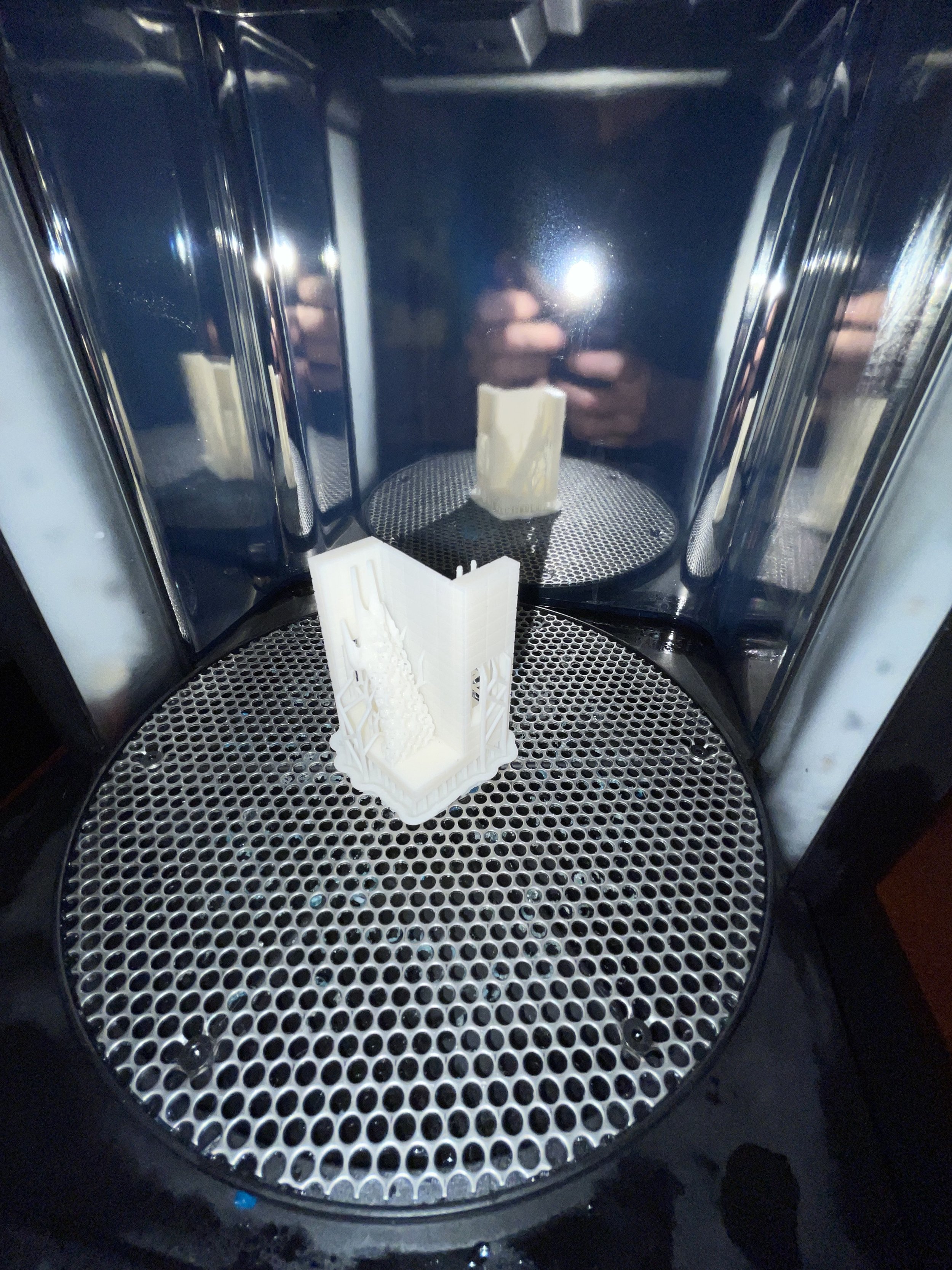
Printing and Prototypes
At last! The fun part is the printing. I did two prototypes. The first time around, I didn’t control where my supports attached and experienced some issues with warping that caused the jail bars to bend and one of my walls to break. Second time around, I made sure no supports attached to exterior faces of my part so I wouldn’t have to do as much post-processing, added the brick texturing, and changed my window lattice to make the bars thicker so they wouldn’t be prone to warping. The second print was satisfactory.