The Automatic Cake Writer
Problem Definition
Challenge
Design and build a 2.5 axis motion system that accomplishes a task of the group’s choosing. The system will consistent of an end effector that can be controlled in two directions. The work volume must be no more than 2.5x2.5x2.5”, the maximum permissible volume in which the end effector is allowed to move. The idea is to create a system that is small and light enough to fit inside a backpack given the current limitations inflicted by COVID on the design and manufacturing environment. Aside from given components, including stepper motors, supporting electronics, and 8020 aluminum extrusion bars to use for structure, all components will be 3D printed.
Constraints
All custom-made parts must be 3D printed
2.5 axis motion system
2.5” cubic maximum work area for end effector
Team Observations
The team observed that the project requirements support the design of some variety of 2-D printing system. We researched designs from past groups, and a member suggested that we design and build a 2-D cake decorator. Given the limitation to 2-D space, the group decided to focus on creating a product that specialized writing letter and numbers on cupcakes
Objectives
Extrude icing onto the flat surface of a cake within a 2.5x2.5” work area
Move the end effector in x and y directions
Control the flow of icing using a single motor
Allow for the re-filling of the end effector with icing when it runs out
Goals
Write distinguishable letters or numbers onto the surface of a pastry
Control the movement of the end effector using two stepper motors
Employ a modular design that allows for easy re-filling of the end effector
Ideals
Create an easy-to-use, 3D printer style extruder with a user-friendly interface that enables programming of complex expressions to be printed onto a variety of pastries
Design and end-effector that requires no user maintenance such a reloading and fine tuning
Ensure consistent size and shape of lettering
Problem Statement
Design and build a two axis motion system with an end effector that is able to print letters and numbers onto a flat pastry surface. The cake decorator must be able to perform motion in the x and y directions and extrude icing from a single point to create letters on the surface of the cake. The system should be able to create distinguishable letters, numbers, and phrases, and control x and y motion with only two stepper motors while being easy to disassemble in order to reload the icing. Ideally, the printer will be easy to use and require minimal user “fiddling” to perform consistently. The system would also ideally give the user a simple user interface to program the extruder.
Conceptual Design
Linear Actuators
The team considered a variety of design concepts to control the x-y linear motion of the system. Initially, we anticipated using a two motor system with belt driven motion, shown in figure 1.
We realized, after presenting our design for review, that there may be issues with the floating bar binding up if its motion was only being controlled by a single belt drive. This realization brought the team back to the drawing board.
To alleviate concerns with binding in the floating bar, the team decided to use an H-bot belt drive design, which would allow for x-y linear control of the system with two stepper motors. The H-bot concept uses two motors and the difference in rotational velocity between the motors to control the motion of the end effector. Instead of having two separate motors and drive systems that are responsible for x and y motion respectively, an H-bot connects two motors and the end effector with one belt and the motion of the end effector is determined by difference in speed between the motors. A conceptual sketch of the H-bot design is shown in figure 2.
End Effector
One of the first major design decisions the group faced was whether to use a store-bought or custom-spec, 3D printed syringe to extrude icing. To present for review, the team came up with two conceptual designs for a customized end effector that could be 3D printed and a concept for mounting and controlling 20mL syringe.
The first custom-built syringe concept (figure 3) used an Archimedes screw design that would connect directly to the stepper motor and squeeze out the icing in a controlled continuous manner. The group noted that the extrusion hole would have to be offset from the center of the syringe due to the nature of the design (an Archimedes screw has a center shaft that supports the rest of the screw).
The second custom-built concept (figure 4) employed a more traditional plunger/cylinder design concept that would use a lead screw mechanism to control the vertical motion of the plunger and thus the extrusion of the icing. The group noted that this design would support a center-hole extrusion, however the nature of a plunger mechanism means that the length of the plunger increases as the height of the tube increases, so the mechanism would take up more space than the Archimedes screw concept. There would also be added complication from converting the rotation of the motor to the desired linear motion of the plunger. It is also important to note that there were considerable concerns about design and building a custom-built extrusion device due to the inaccuracies present in 3D printing. The group noted that it would be very difficult to get a good seal between the plunger or the screw and the inner walls of the extruder that may result in poor performance, or even failure to perform at all.
The group also came up with a mounting and actuating concept to work with a common 20mL medical syringe (figure 5). This concept uses a lead screw mechanism that connects via a floating plate to the top of the syringe. As the lead screw turns, the floating plate moves up and down to actuate the syringe and control the output of icing. The group noted this design to be advantageous because it alleviates concerns about the performance of the syringe. However, this concept does have the same height limitation as the second custom-built concept in addition to added concerns with the added complexity of modifying the syringe/connecting the syringe to the lead screw assembly.
Preliminary Design
After consulting on conceptual designs, the group decided to employ an H-bot belt drive to control the motion of the end effector. The team also decided that it would be best to use a 20mL syringe with a lead screw device designed to operate the plunger in order to ensure that it would be feasible to construct a prototype in the given timeframe. Next, preliminary designs were drawn for the end effector and frame of the device based on the size of the 20mL syringe.
End Effector
The preliminary design of the end effector used a top and bottom mounting plate assembly to secure the syringe by the built-in handles. The syringe slides into a hole in the bottom plate and the handles fit into a rectangular cut partially into in the top of the plate. The top plate has a rectangular through-cut that allows the handle of the plunger to move freely while securing the handles of the syringe from moving upward. The top and bottom plate are held together by two screws on the back of the plate. The top plate also featured a 3mm through hole cut to secure the lead screw in the x and y directions. The top plate originally also had a 1.5mm through hole to seat a guiding rod that would secure the floating plate from spinning freely with the lead screw. The floating plate preliminary design featured a receptacle for the lead screw to connect to the plate and a separate plate to push down on the handle of the syringe. The last piece in the preliminary design was a top plate to secure the stepper motor that would control the motion of the lead screw (figure 6,7).
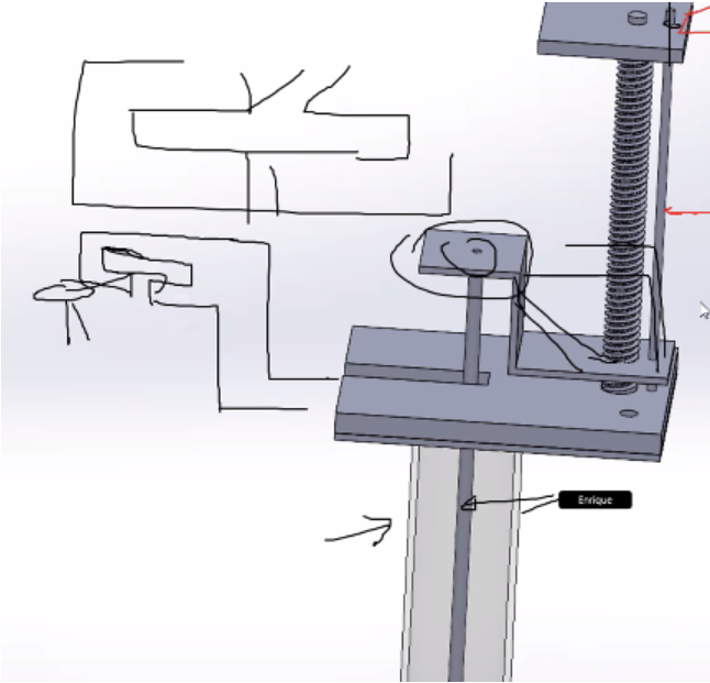
Figure 7. End Effector Preliminary Design with Notes from Professor Gutierrez
Detailed Design
Frame Assembly
The frame was designed allow for 2.5x2.5” work area of the end effector. This means that the tip of the end effector needs to be able to accomplish 2.5” of travel in either direction. To accomplish this, the inside width of the frame was calculated by adding the width of the end effector mounting plates to 2.5". To find the inside length of the frame, the distance between the tip of the end effector and the front-most face of the end effector plates was measured, and the distance between the tip of the end effector and the center of the end effector slider was measured, then both of these dimensions were added to 2.5” (drawing 1)
End Effector Assembly
The end effector design changed after initial prototypes were constructed and issues were addressed throughout construction. A lot of issues could be attributed to 3D printing errors and small changes were made to improve the quality of finished prints. In addition, slight modifications were made to correct poorly estimated fits for certain pieces including the hole on the bottom plate for the syringe. The major change from preliminary to final design of the product was the inclusion of the built-in slider on the bottom plate of the assembly. Initially the team planned to use screws as an attachment to the floating frame rail, but it was discovered that the custom-made sliders were much more effective. The top plate was also modified to include an attachment point for the belt from the H-bot linear drive. The dowel rod was also replaced with two 3D printed supports (drawings 2-7)
H-Bot Assembly
The H-bot assembly saw some minor tweaks throughout prototyping. The final design included 3D printed motor mounted, top plates, and end plates to secure free-moving pulleys. The motor mounts attached to the frame using two screws for each mount, and the top plates were attached directly to the motors using screws to help secure the motors while the cake decorator was in motion. The end-plates were screwed into the included holes in the 8020 frame bars that were tapped with 1/4-20 threads (figure 7).
Control using G-Code and Repetier
To control the motion of the system, the team used a supplied PCB which was designed to control custom-built 3D printers. First, the team had to modify the firmware on the board for it to be compatible with an H-bot linear drive mechanism. To do this, the team used Repetier’s tool to build custom firmware, and uploaded it to the board using the Arduino IDE. Once the firmware was uploaded to the board, Repetier Host could be used to control the Cake Writer just like it would be used to control a conventional 3D printer.
To create a profile to generate G-Code, the team extruded writing in Solidworks and saved it as an STL file. The STL file was then imported to Repetier host, positioned, and sliced using custom settings in the Slic3r engine. The team then modified the G-code so it would only direct the writer to print a single layer and single line version of what the built-in Slic3r outputted. Using this method, the team was able to successfully control the Cake Writer and write a “0” on a flat surface (figure 8).
Final Prototype
The final prototype was a rewarding accomplishment. A lot was learned throughout the construction of the first Cake Writer, and many of those lessons were applied as the design was brought into reality in order to ensure the prototype could achieve basic functionality. However, some lessons were not able to be applied by the time the demonstration rolled around. Most notably, the end effector was very sensitive to viscosity of the icing being employed. Not only was it difficult to calibrate the extrusion rate to get legible, meaningful writing, the floating plate actually broke when the extruder was unable to squeeze out a rather viscous variety of icing. A lead screw assembly that would be positioned more close to the center of the plunger would make a significant difference to the reliability of the assembly. To reach a final design, it would take at least one more prototype to iron out the kinks with the extruder, but I’m confident that this design could actually be a viable product.